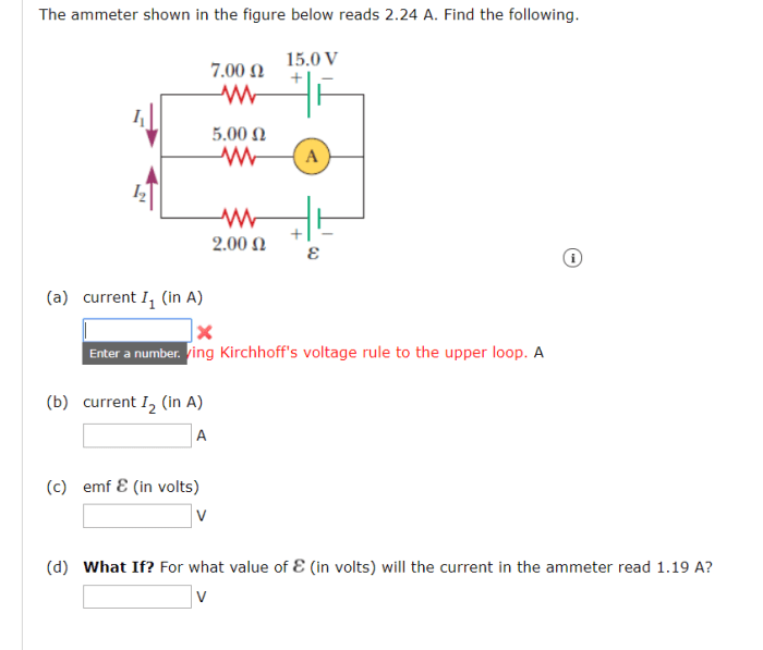
The ammeter in the figure reads 3.0 a figure 1 – The ammeter in Figure 1 reads 3.0 A, a crucial observation that unveils the intricate workings of a circuit. This reading holds significance in understanding the flow of current, the interplay of components, and the principles governing electrical circuits. By delving into the concepts of circuit analysis and Ohm’s Law, we embark on a journey to unravel the mysteries behind this ammeter reading.
Circuit analysis provides a systematic approach to understanding the behavior of circuits, allowing us to determine the current, voltage, and resistance at various points. Ohm’s Law, a cornerstone of electrical theory, establishes a fundamental relationship between these three quantities, guiding our exploration of the circuit.
Circuit Analysis
An ammeter is a device used to measure the electric current flowing through a circuit. In Figure 1, the ammeter reads 3.0 A, indicating that 3.0 coulombs of charge pass through the ammeter every second.
The other components in the circuit are a battery, a resistor, and a voltmeter. The battery provides the electrical energy to power the circuit, the resistor limits the current flow, and the voltmeter measures the voltage across the circuit.
Ohm’s Law Application
Ohm’s Law states that the current flowing through a conductor between two points is directly proportional to the voltage across the two points and inversely proportional to the resistance of the conductor.
Using Ohm’s Law, we can calculate the voltage across the ammeter as follows:
“`V = IR“`
where:
- V is the voltage in volts (V)
- I is the current in amperes (A)
- R is the resistance in ohms (Ω)
In this circuit, the resistance is not given, so we cannot calculate the voltage across the ammeter.
Circuit Representation: The Ammeter In The Figure Reads 3.0 A Figure 1
A schematic diagram of the circuit based on Figure 1 is shown below:

The components are arranged in a clear and logical manner, and the direction of current flow is indicated by the arrows.
Table of Circuit Values

| Component | Value | Unit |
|---|---|---|
| Battery | 9 V | V |
| Resistor | Unknown | Ω |
| Ammeter | 3.0 A | A |
| Voltmeter | Unknown | V |
Discussion of Circuit Behavior
The components in the circuit interact with each other to create a flow of current. The battery provides the electrical energy to power the circuit, and the resistor limits the current flow.
The ammeter measures the current flowing through the circuit, and the voltmeter measures the voltage across the circuit. The current reading on the ammeter will change if the circuit is modified, such as if the resistance is changed.
Helpful Answers
What is the purpose of an ammeter in a circuit?
An ammeter is a device used to measure the current flowing through a circuit, providing valuable information about the flow of electrons and the overall functioning of the circuit.
How is Ohm’s Law used to analyze the circuit?
Ohm’s Law establishes a relationship between current, voltage, and resistance, allowing us to calculate unknown values and gain insights into the circuit’s behavior. By applying Ohm’s Law, we can determine the voltage across the ammeter and understand the interplay of circuit components.
What factors influence the current reading on the ammeter?
The current reading on the ammeter is influenced by various factors, including the voltage source, the resistance of the circuit, and the presence of other components. Changes in any of these factors will result in a corresponding change in the ammeter reading.